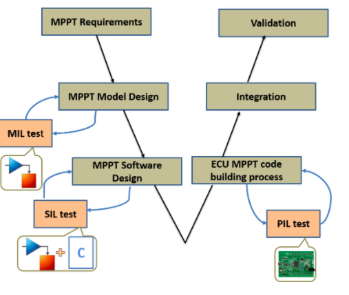
This work develops a modified Maximum Power Point Tracking controller as the automotive and aeronautical systems are developed. According to ISO26262 and DO-178C respectively. Therefore, the V-model development process has been followed (Figure 1). That means that our controller will be validated using Model in the loop/Software in the loop/ Processor in the loop tests. Hence, this works can be used as a reference to integrate the photovoltaic energy in automotive or aeronautical fields. In addition, Processor in the loop test presented in this work can be used as a low-cost solution to test the hardware implementation of MPPT algorithms.

Figure 1. MPPT development process through V-model.
This work presents guidelines to develop the Maximum Power Point Tracking controller, as developed in the automotive and aeronautical systems, this by following the V-model development process. Which means that our controller will be validated by using Model In the Loop/ Software In the Loop/Processor In the Loop tests to have the possibility of integrating the MPPT embedded software in automotive and aeronautical areas. On the other hand, propose a low-cost option to test the hardware implementation of the MPPT algorithm using PIL approach. Therefore, a modified variable step Incremental Conductance algorithm is proposed in this study, which can reduce the steady-state oscillations and increase the tracking speed under sudden irradiance variation. Then, the Model-based design of the modified algorithm is developed and connected to the plant model (photovoltaic panel and Boost converter). Next, the system model is tested and validated by using Model In the Loop process. After that, the software of this algorithm is automatically generated for the host computer using embedded coder tool, and this software is connected to the plant model and tested using Software in the Loop process in the host computer. Finally, the software is generated from the MPPT model for the STM32F4 discovery board in order to create the Processor In the Loop block, which will be run in the STM32F4 discovery board, and the plant model will be simulated in the host computer, and the ST-LINK communication is used in order to connect the host computer and the embedded board (Figure 2).
Figure 2. The PV system under test using PIL validation approach.
Three manners of tests (MIL/SIL/PIL) mostly used for automotive and aeronautical embedded system are employed in this work, that in order to validate the functionality and robustness of the modified variable step INC algorithm. As a result, the responses of the three tests are in accordance with the MPPT algorithm requirements, as well as this work contributes to achieve the objective of DO-178C compliance. In addition, the results show that the modified algorithm avoids the steady-state oscillations and increases the tracking speed under sudden irradiance variation. In the light of that, the MPPT is tested on STM32F4 Discovery board; therefore, the performance obtained will be the same by using a real PV panel. Subsequently, the PIL test can be used as a low-cost solution to test the hardware implementation of MPPT algorithms, as well as the control of renewable energy and power electronic systems.
So, by using these kinds of tests, we took advantage of safety level integrated in automotive and aeronautical embedded system, and note that by using this work, the MPPT controller can be integrated in the aeronautical and automotive areas.
For more information, please, refer to the full paper.
Tags: Solar Energy, MPPT, DO-178C, ISO 26262, V-model, Embedded Coder
Saad Motahhir – (ENSA, SMBA University, Fez, Morocco)